
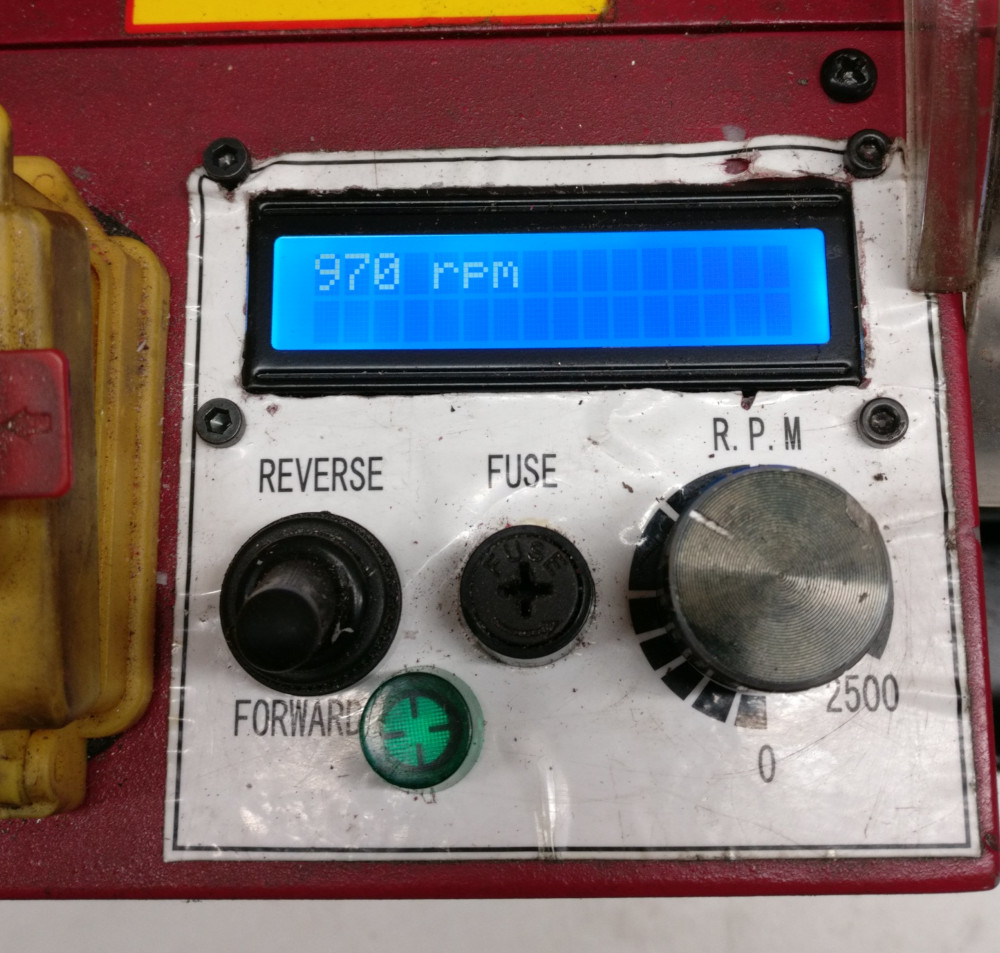
Cutting the window for the screen and putting the screws in the right place was quite a challenge because I could not move the enclosure to my mini-mill: it was to tall. I cut the window freehand with a Dremel tool. The following image shows the back of the LCD screen mounted on the top surface of the enclosure. It takes the location of the green power light, the yellow fault light, and the LCD socket.

One can hardly see in the previous image the green power light that was moved below the forward/reverse switch and the main fuse. Desoldering the green power light and resoldering the wires after the move was also tricky as the other end of the wires is connected to other wires, thus preventing the soldering operation to be performed conveniently: one as to do it within the enclosure. I later noticed that I cut the window for the LCD screen slightly too close to the opening
(i.e. too close to the spindle). When mounting the enclosure back to the headstock, it almost
touches it.
As is, it works, thanks a lot to @Jenny for sharing this, it helped me tremendously.
For my training, though, I think I will continue to investigate the software changes I wanted to make initially, perhaps using a more powerful board. I purchased the nano boards from China using Ali Express marketplace. The boards costed only 2€ each (maybe this is the reason the boards cannot keep up…). I will try with other boards I purchased from Mouser the ESP32 pico Kit <https://www.mouser.fr/_/?Keyword=ESP32-PICO-KIT>. The provider is more reliable and the ESP32 is far more beefy, probably even overkill for this application. The cost also remains very reasonable (8.73€). Programming is quite different from Arduino, so I will have to change a lot of things.